Back to Labs & Projects

Cisco Packet Tracer

Cisco Networking Lab

Three completed labs using simulated networks to practise IP addressing, connectivity troubleshooting, and router and switch configuration.

Troubleshooting IPv4 and IPv6 connectivity

Lab goal
Use ICMP to test reachability across a simulated multi-router network and correct connectivity problems.
What I configured or checked

I started with an ICMP ping inside the LAN, then tested IPv6 reachability between networks. Ping and traceroute were my main troubleshooting tools. I used ping to check reachability, traceroute to trace the path toward remote destinations, and Cisco IOS commands to inspect interface status and routing tables and make configuration changes.

  1. Switch interface down

    The first ping failed within the LAN. A switch interface was down, so traffic wasn’t getting through.

    I brought the interface up in IOS.

    no shutdown

    Repeat test. I reran the same LAN ping and confirmed traffic was getting through.

  2. PC-2 had the wrong IPv6 gateway

    PC-2 couldn’t ping the corporate server. I checked the PC’s IP configuration and found that its default gateway was wrong.

    I set the gateway to RTR-2’s LAN address from the lab addressing table.

    Repeat test. PC-2 received replies when I pinged the corporate server again.

  3. RTR-3 had the wrong LAN prefix

    Hosts on the :5::/64 LAN couldn’t reach remote networks. I checked the IPv6 routing table on each router. RTR-3 lacked the expected route for that LAN, and its interface summary showed an address in :6::/64.

    I corrected the IPv6 address on RTR-3’s LAN interface to match the :5::/64 subnet in the addressing table.

    show ipv6 routeshow ipv6 interface brief

    Repeat test. From the :5::/64 LAN, I successfully pinged both PC-2 and the corporate server.

How I verified it
The repeat tests confirmed reachability within the LAN and across the IPv6 networks I’d troubleshot. I saved the configuration changes.
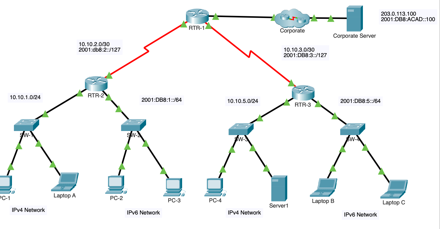
Three routers connect four IPv4 and IPv6 LANs through access switches to a simulated corporate server.
Multi-router topology with IPv4 and IPv6 LANs and a simulated corporate network.
Key lab addresses
IPv4 LANs10.10.1.0/24 and 10.10.5.0/24
IPv6 LANs2001:db8:1::/64 and 2001:db8:5::/64
Corporate server203.0.113.100 and 2001:db8:acad::100

Troubleshooting connectivity between two IPv4 subnets

Lab goal
Use the network documentation to isolate and correct reachability problems between two IPv4 LANs connected by one router.
What I configured or checked

I tested connectivity in stages. I started with a host on the same LAN, then tested the remote subnet and used the failed gateway ping to decide what to check next.

  1. PC1 had an IP address from the wrong subnet

    PC1 couldn’t ping PC2 on the same LAN. I checked both PCs’ IP settings against the addressing table and found that PC1’s address was on a different subnet.

    I corrected PC1’s address to 192.168.10.10/24, as listed in the table.

    Repeat test. PC1 received replies from PC2.

  2. R1 and PC3 needed gateway configuration

    PC1 could reach PC2 but still couldn’t ping PC3 on the other subnet. I pinged R1’s local gateway address from PC1 and got no reply. I checked R1 in IOS and found that its IP configuration was missing.

    I configured R1’s LAN interfaces using the addressing table. I then checked PC3’s IPv4 settings and corrected its default gateway to 192.168.11.1, the R1 address on PC3’s subnet.

    Repeat test. PC1 successfully pinged PC3 after both changes.

How I verified it
The PC1-to-PC2 ping confirmed local connectivity. The PC1-to-PC3 ping confirmed the cross-subnet path through R1, including the return path from PC3.
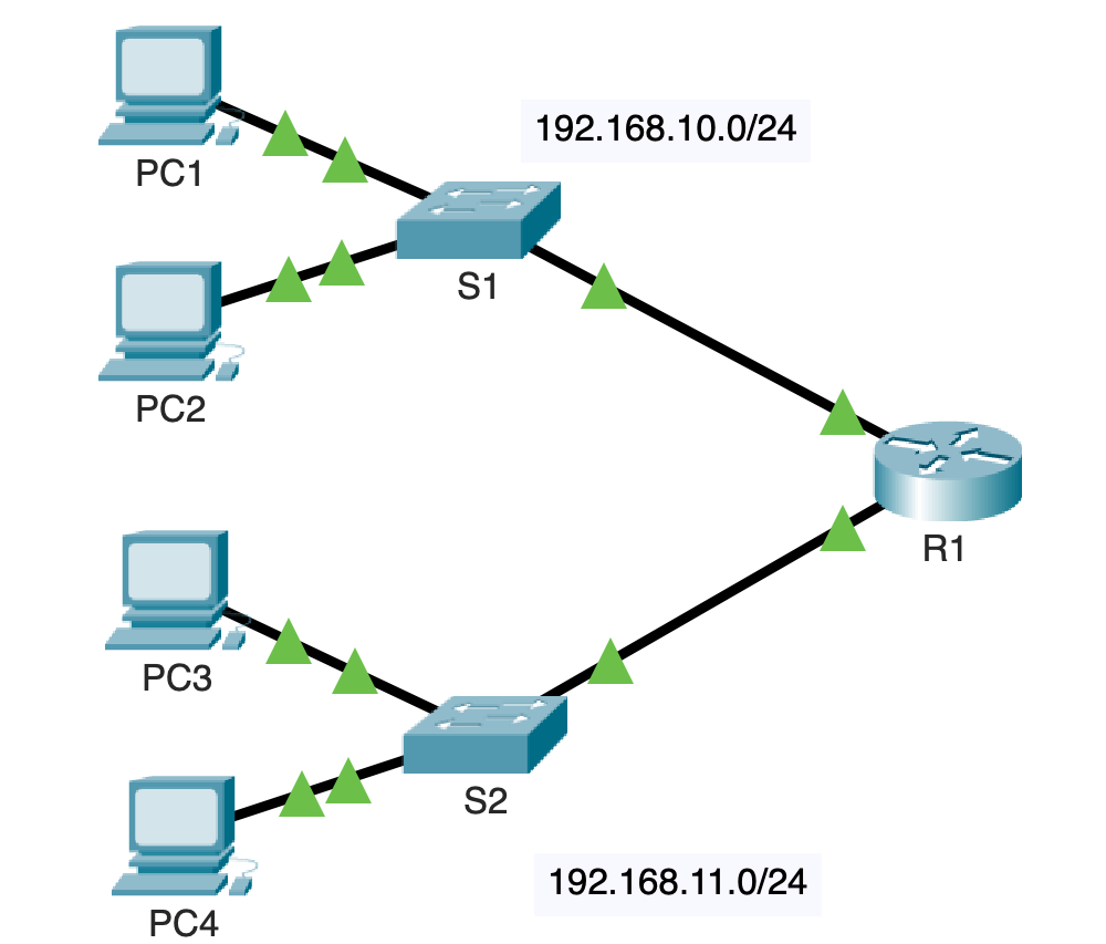
Router R1 connects two switched LANs, each with two PCs, on 192.168.10.0/24 and 192.168.11.0/24.
Two IPv4 LANs connected through R1, with two PCs on each LAN.
Key lab addresses
192.168.10.0/24R1 G0/0 · 192.168.10.1
192.168.11.0/24R1 G0/1 · 192.168.11.1

R1 configuration example

IOS workflow based on the lab’s addressing table.

enable
configure terminal
interface GigabitEthernet0/0
 ip address 192.168.10.1 255.255.255.0
 no shutdown
 exit
interface GigabitEthernet0/1
 ip address 192.168.11.1 255.255.255.0
 no shutdown
end
show ip interface brief

Building a switch and router network

Lab goal
Connect two PCs on separate IPv4 subnets through a router and set up SSH access to the router and switch.
What I configured or checked

I built and cabled the topology first, then worked from the lab addressing table to configure each device.

  1. Cable the topology

    I placed PC-A, PC-B, S1 and R1 in Packet Tracer. I used straight-through Ethernet cables for PC-A to S1, S1 to R1, and R1 to PC-B.

  2. Configure the two PCs

    I assigned the IPv4 address, subnet mask and default gateway on each PC. PC-A used 192.168.1.1 as its gateway and PC-B used 192.168.0.1.

  3. Bring up both R1 interfaces

    I assigned 192.168.0.1/24 to G0/0/0 and 192.168.1.1/24 to G0/0/1, then enabled each interface with no shutdown.

  4. Configure switch management and remote access

    I set S1’s VLAN 1 management address to 192.168.1.2/24 and its default gateway to 192.168.1.1. On both S1 and R1, I enabled SSH for remote management and ran service password-encryption for passwords in the IOS configuration.

How I verified it
PC-A received ping replies from PC-B, confirming connectivity across the two subnets. From PC-B, I successfully logged in over SSH to both R1 and S1.
PC A connects to switch S1, which connects to router R1. PC B connects directly to the router.
Packet Tracer topology showing the path from PC A through S1 and R1 to PC B.
Key lab addresses
192.168.1.0/24PC A · 192.168.1.3 · gateway 192.168.1.1
192.168.0.0/24PC B · 192.168.0.3 · gateway 192.168.0.1
S1 VLAN 1192.168.1.2/24 · gateway 192.168.1.1

R1 configuration example

IOS workflow based on the lab’s addressing table.

enable
configure terminal
interface GigabitEthernet0/0/0
 ip address 192.168.0.1 255.255.255.0
 no shutdown
 exit
interface GigabitEthernet0/0/1
 ip address 192.168.1.1 255.255.255.0
 no shutdown
 exit
end
show ip interface brief